Lithium-ion batteries are mainly developing in the direction of high energy density. At room temperature, silicon-based negative electrode materials alloy with lithium to produce lithium-rich product Li3.75Si phase, with a specific capacity of up to 3572 mAh/g, which is much higher than the theoretical specific capacity of graphite negative electrode 372 mAh/g. However, during the repeated charging and discharging process of silicon-based negative electrode materials, the phase transformation of Si and Li3.75Si can produce huge volume expansion (about 300%), which will lead to structural powdering of electrode materials and continuous formation of SEI film, and finally cause the capacity to drop rapidly. The industry mainly improves the performance of silicon-based negative electrode materials and the stability of silicon-based batteries through nano-sizing, carbon coating, pore formation and other technologies.
Carbon materials have good conductivity, low cost, and wide sources. They can improve the conductivity and surface stability of silicon-based materials. They are preferentially used as performance improvement additives for silicon-based negative electrodes. Silicon-carbon materials are the mainstream development direction of silicon-based negative electrodes. Carbon coating can improve the surface stability of silicon-based materials, but its ability to inhibit silicon volume expansion is general and cannot solve the problem of silicon volume expansion. Therefore, in order to improve the stability of silicon-based materials, porous structures need to be constructed. Ball milling is an industrialized method for preparing nanomaterials. Different additives or material components can be added to the slurry obtained by ball milling according to the design requirements of the composite material. The slurry is evenly dispersed through various slurries and spray-dried. During the instantaneous drying process, the nanoparticles and other components in the slurry will spontaneously form porous structural characteristics. This paper uses industrialized and environmentally friendly ball milling and spray drying technology to prepare porous silicon-based materials.
The performance of silicon-based materials can also be improved by regulating the morphology and distribution characteristics of silicon nanomaterials. At present, silicon-based materials with various morphologies and distribution characteristics have been prepared, such as silicon nanorods, porous graphite embedded nanosilicon, nanosilicon distributed in carbon spheres, silicon/graphene array porous structures, etc. At the same scale, compared with nanoparticles, nanosheets can better suppress the crushing problem caused by volume expansion, and the material has a higher compaction density. The disordered stacking of nanosheets can also form a porous structure. To join the silicon negative electrode exchange group. Provide a buffer space for the volume expansion of silicon materials. The introduction of carbon nanotubes (CNTs) can not only improve the conductivity of the material, but also promote the formation of porous structures of the material due to its one-dimensional morphological characteristics. There are no reports on porous structures constructed by silicon nanosheets and CNTs. This paper adopts the industrially applicable ball milling, grinding and dispersion, spray drying, carbon pre-coating and calcination methods, and introduces porous promoters in the preparation process to prepare porous silicon-based negative electrode materials formed by self-assembly of silicon nanosheets and CNTs. The preparation process is simple, environmentally friendly, and no waste liquid or waste residue is generated. There are many literature reports on carbon coating of silicon-based materials, but there are few in-depth discussions on the effect of coating. This paper uses asphalt as the carbon source to investigate the effects of two carbon coating methods, liquid phase coating and solid phase coating, on the coating effect and the performance of silicon-based negative electrode materials.
1 Experiment
1.1 Material preparation
The preparation of porous silicon-carbon composite materials mainly includes five steps: ball milling, grinding and dispersion, spray drying, carbon pre-coating and carbonization. First, weigh 500 g of initial silicon powder (domestic, 99.99% purity), add 2000 g of isopropanol, and perform wet ball milling at a ball milling speed of 2000 r/min for 24 h to obtain nano-scale silicon slurry. The obtained silicon slurry is transferred to a dispersion transfer tank, and the materials are added according to the mass ratio of silicon: graphite (produced in Shanghai, battery grade): carbon nanotubes (produced in Tianjin, battery grade): polyvinyl pyrrolidone (produced in Tianjin, analytical grade) = 40:60:1.5:2. Isopropanol is used to adjust the solid content, and the solid content is designed to be 15%. Grinding and dispersion are performed at a dispersion speed of 3500 r/min for 4 h. Another group of slurries without adding CNTs is compared, and the other materials are the same. The obtained dispersed slurry is then transferred to a spray drying feeding tank, and spray drying is performed in a nitrogen-protected atmosphere, with the inlet and outlet temperatures being 180 and 90 °C, respectively. Then two types of carbon coating were compared, solid phase coating and liquid phase coating. The solid phase coating method is: the spray-dried powder is mixed with 20% asphalt powder (made in Korea, D50 is 5 μm), mixed in a mechanical mixer for 10 min, and the mixing speed is 2000 r/min to obtain pre-coated powder. The liquid phase coating method is: the spray-dried powder is added to a xylene solution (made in Tianjin, analytical grade) containing 20% asphalt dissolved in the powder at a solid content of 55%, and vacuum stirred evenly. Bake in a vacuum oven at 85℃ for 4h, put into a mechanical mixer for mixing, the mixing speed is 2000 r/min, and the mixing time is 10 min to obtain pre-coated powder. Finally, the pre-coated powder was calcined in a rotary kiln under a nitrogen atmosphere at a heating rate of 5°C/min. It was first kept at a constant temperature of 550°C for 2h, then continued to heat up to 800°C and kept at a constant temperature for 2h, and then naturally cooled to below 100°C and discharged to obtain a silicon-carbon composite material.
1.2 Characterization methods
The particle size distribution of the material was analyzed using a particle size tester (Mastersizer 2000 version, made in the UK). The powders obtained in each step were tested by scanning electron microscopy (Regulus8220, made in Japan) to examine the morphology and size of the powders. The phase structure of the material was analyzed using an X-ray powder diffraction analyzer (D8 ADVANCE, made in Germany), and the elemental composition of the material was analyzed using an energy spectrum analyzer. The obtained silicon-carbon composite material was used to make a button half-cell of model CR2032, and the mass ratio of silicon-carbon: SP: CNT: CMC: SBR was 92:2:2:1.5:2.5. The counter electrode is a metal lithium sheet, the electrolyte is a commercial electrolyte (model 1901, made in Korea), Celgard 2320 diaphragm is used, the charge and discharge voltage range is 0.005-1.5 V, the charge and discharge current is 0.1 C (1C = 1A), and the discharge cut-off current is 0.05 C.
In order to further investigate the performance of silicon-carbon composite materials, laminated small soft-pack battery 408595 was made. The positive electrode uses NCM811 (made in Hunan, battery grade), and the negative electrode graphite is doped with 8% silicon-carbon material. The positive electrode slurry formula is 96% NCM811, 1.2% polyvinylidene fluoride (PVDF), 2% conductive agent SP, 0.8% CNT, and NMP is used as a dispersant; the negative electrode slurry formula is 96% composite negative electrode material, 1.3% CMC, 1.5% SBR 1.2% CNT, and water is used as a dispersant. After stirring, coating, rolling, cutting, lamination, tab welding, packaging, baking, liquid injection, formation and capacity division, 408595 laminated small soft pack batteries with a rated capacity of 3 Ah were prepared. The rate performance of 0.2C, 0.5C, 1C, 2C and 3C and the cycle performance of 0.5C charge and 1C discharge were tested. The charge and discharge voltage range was 2.8-4.2 V, constant current and constant voltage charging, and the cut-off current was 0.5C.
2 Results and Discussion
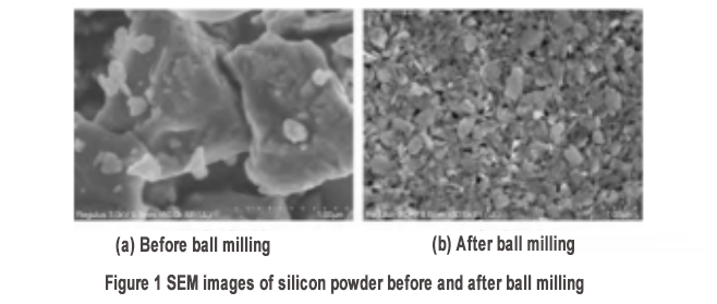
The initial silicon powder was observed by scanning electron microscopy (SEM). The silicon powder was irregularly granular with a particle size of less than 2μm, as shown in Figure 1(a). After ball milling, the size of the silicon powder was significantly reduced to about 100 nm [Figure 1(b)]. The particle size test showed that the D50 of the silicon powder after ball milling was 110 nm and the D90 was 175 nm. A careful examination of the morphology of silicon powder after ball milling shows a flaky structure (the formation of the flaky structure will be further verified from the cross-sectional SEM later). Therefore, the D90 data obtained from the particle size test should be the length dimension of the nanosheet. Combined with the SEM results, it can be judged that the size of the obtained nanosheet is smaller than the critical value of 150 nm of the breakage of silicon powder during charging and discharging in at least one dimension. The formation of the flaky morphology is mainly due to the different dissociation energies of the crystal planes of crystalline silicon, among which the {111} plane of silicon has a lower dissociation energy than the {100} and {110} crystal planes. Therefore, this crystal plane is more easily thinned by ball milling, and finally forms a flaky structure. The flaky structure is conducive to the accumulation of loose structures, reserves space for the volume expansion of silicon, and improves the stability of the material.
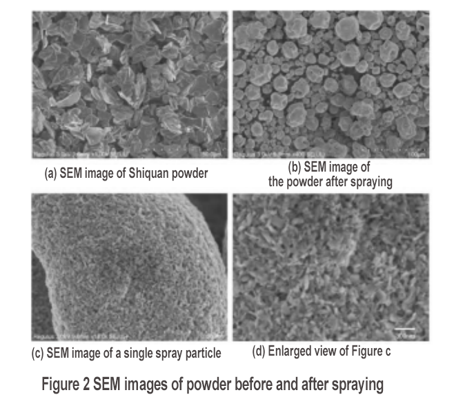
The slurry containing nano-silicon, CNT and graphite was sprayed, and the powder before and after spraying was examined by SEM. The results are shown in Figure 2. The graphite matrix added before spraying is a typical flake structure with a size of 5 to 20 μm [Figure 2(a)]. The particle size distribution test of graphite shows that D50 is 15μm. The powder obtained after spraying has a spherical morphology [Figure 2(b)], and it can be seen that the graphite is coated by the coating layer after spraying. The D50 of the powder after spraying is 26.2 μm. The morphological characteristics of the secondary particles were observed by SEM, showing the characteristics of a loose porous structure accumulated by nanomaterials [Figure 2(c)]. The porous structure is composed of silicon nanosheets and CNTs intertwined with each other [Figure 2(d)], and the test specific surface area (BET) is as high as 53.3 m2/g. Therefore, after spraying, silicon nanosheets and CNTs self-assemble to form a porous structure.
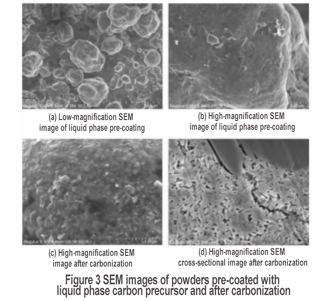
The porous layer was treated with liquid carbon coating, and after adding carbon coating precursor pitch and carbonization, SEM observation was carried out. The results are shown in Figure 3. After carbon pre-coating, the surface of the secondary particles becomes smooth, with an obvious coating layer, and the coating is complete, as shown in Figures 3(a) and (b). After carbonization, the surface coating layer maintains a good coating state [Figure 3(c)]. In addition, the cross-sectional SEM image shows strip-shaped nanoparticles [Figure 3(d)], which correspond to the morphological characteristics of nanosheets, further verifying the formation of silicon nanosheets after ball milling. In addition, Figure 3(d) shows that there are fillers between some nanosheets. This is mainly due to the use of liquid phase coating method. The asphalt solution will penetrate into the material, so that the surface of the internal silicon nanosheets obtains a carbon coating protective layer. Therefore, by using liquid phase coating, in addition to obtaining the secondary particle coating effect, the double carbon coating effect of primary particle coating can also be obtained. The carbonized powder was tested by BET, and the test result was 22.3 m2/g.
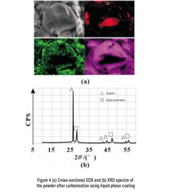
The carbonized powder was subjected to cross-sectional energy spectrum analysis (EDS), and the results are shown in Figure 4(a). The micron-sized core is C component, corresponding to the graphite matrix, and the outer coating contains silicon and oxygen. To further investigate the structure of silicon, an X-ray diffraction (XRD) test was performed, and the results are shown in Figure 4(b). The material is mainly composed of graphite and single-crystal silicon, with no obvious silicon oxide characteristics, indicating that the oxygen component of the energy spectrum test mainly comes from the natural oxidation of the silicon surface. The silicon-carbon composite material is recorded as S1.
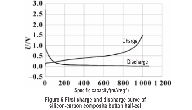
The prepared silicon-carbon material S1 was subjected to button-type half-cell production and charge-discharge tests. The first charge-discharge curve is shown in Figure 5. The reversible specific capacity is 1000.8 mAh/g, and the first cycle efficiency is as high as 93.9%, which is higher than the first efficiency of most silicon-based materials without pre-lithiation reported in the literature. The high first efficiency indicates that the prepared silicon-carbon composite material has high stability. In order to verify the effects of porous structure, conductive network and carbon coating on the stability of silicon-carbon materials, two types of silicon-carbon materials were prepared without adding CNT and without primary carbon coating.
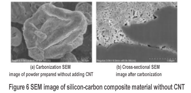
The morphology of the carbonized powder of the silicon-carbon composite material without adding CNT is shown in Figure 6. After liquid phase coating and carbonization, a coating layer can be clearly seen on the surface of the secondary particles in Figure 6(a). The cross-sectional SEM of the carbonized material is shown in Figure 6(b). The stacking of silicon nanosheets has porous characteristics, and the BET test is 16.6 m2/g. However, compared with the case with CNT [as shown in Figure 3(d), the BET test of its carbonized powder is 22.3 m2/g], the internal nano-silicon stacking density is higher, indicating that the addition of CNT can promote the formation of a porous structure. In addition, the material does not have a three-dimensional conductive network constructed by CNT. The silicon-carbon composite material is recorded as S2.
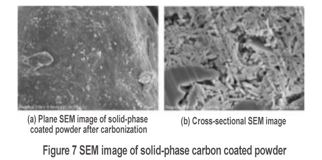
The morphological characteristics of the silicon-carbon composite material prepared by solid-phase carbon coating are shown in Figure 7. After carbonization, there is an obvious coating layer on the surface, as shown in Figure 7(a). Figure 7(b) shows that there are strip-shaped nanoparticles in the cross section, which corresponds to the morphological characteristics of nanosheets. The accumulation of nanosheets forms a porous structure. There is no obvious filler on the surface of the internal nanosheets, indicating that the solid-phase carbon coating only forms a carbon coating layer with a porous structure, and there is no internal coating layer for the silicon nanosheets. This silicon-carbon composite material is recorded as S3.
The button-type half-cell charge and discharge test was conducted on S2 and S3. The specific capacity and first efficiency of S2 were 1120.2 mAh/g and 84.8%, respectively, and the specific capacity and first efficiency of S3 were 882.5 mAh/g and 82.9%, respectively. The specific capacity and first efficiency of the solid-phase coated S3 sample were the lowest, indicating that only the carbon coating of the porous structure was performed, and the carbon coating of the internal silicon nanosheets was not performed, which could not give full play to the specific capacity of the silicon-based material and could not protect the surface of the silicon-based material. The first efficiency of the S2 sample without CNT was also lower than that of the silicon-carbon composite material containing CNT, indicating that on the basis of a good coating layer, the conductive network and a higher degree of porous structure are conducive to the improvement of the charge and discharge efficiency of the silicon-carbon material.
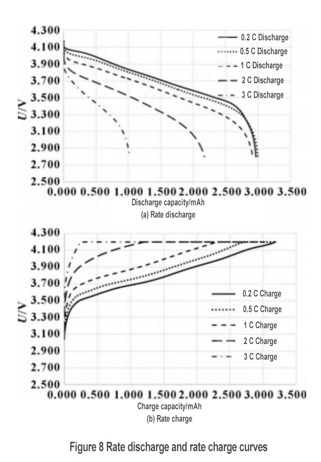
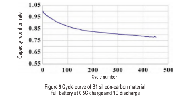
The S1 silicon-carbon material was used to make a small soft-pack full battery to examine the rate performance and cycle performance. The discharge rate curve is shown in Figure 8(a). The discharge capacities of 0.2C, 0.5C, 1C, 2C and 3C are 2.970, 2.999, 2.920, 2.176 and 1.021 Ah, respectively. The 1C discharge rate is as high as 98.3%, but the 2C discharge rate drops to 73.3%, and the 3C discharge rate drops further to 34.4%. To join the silicon negative electrode exchange group, please add WeChat: shimobang. In terms of charging rate, the 0.2C, 0.5C, 1C, 2C and 3C charging capacities are 3.186, 3.182, 3.081, 2.686 and 2.289 Ah, respectively. The 1C charging rate is 96.7%, and the 2C charging rate still reaches 84.3%. However, observing the charging curve in Figure 8(b), the 2C charging platform is significantly larger than the 1C charging platform, and its constant voltage charging capacity accounts for most (55%), indicating that the polarization of the 2C rechargeable battery is already very large. The silicon-carbon material has good charging and discharging performance at 1C, but the structural characteristics of the material need to be further improved to achieve higher rate performance. As shown in Figure 9, after 450 cycles, the capacity retention rate is 78%, showing good cycle performance.
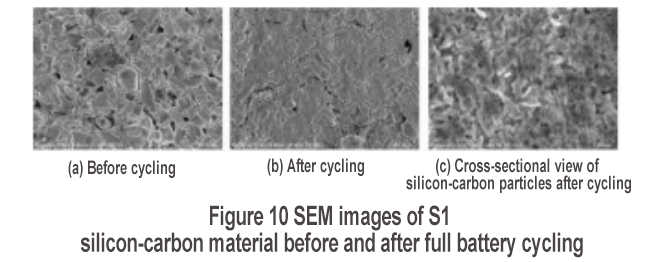
The surface state of the electrode before and after the cycle was investigated by SEM, and the results are shown in Figure 10. Before the cycle, the surface of the graphite and silicon-carbon materials is clear [Figure 10(a)]; after the cycle, a coating layer is obviously generated on the surface [Figure 10(b)], which is a thick SEI film. SEI film roughnessThe active lithium consumption is high, which is not conducive to the cycle performance. Therefore, promoting the formation of a smooth SEI film (such as artificial SEI film construction, adding suitable electrolyte additives, etc.) can improve the cycle performance. The cross-sectional SEM observation of the silicon-carbon particles after the cycle [Figure 10(c)] shows that the original strip-shaped silicon nanoparticles have become coarser and the porous structure has been basically eliminated. This is mainly due to the continuous volume expansion and contraction of the silicon-carbon material during the cycle. Therefore, the porous structure needs to be further enhanced to provide sufficient buffer space for the volume expansion of the silicon-based material.
3 Conclusion
Based on the volume expansion, poor conductivity and poor interface stability of silicon-based negative electrode materials, this paper makes targeted improvements, from the morphology shaping of silicon nanosheets, porous structure construction, conductive network construction and complete carbon coating of the entire secondary particles, to improve the stability of silicon-based negative electrode materials as a whole. The accumulation of silicon nanosheets can form a porous structure. The introduction of CNT will further promote the formation of a porous structure. The silicon-carbon composite material prepared by liquid phase coating has a double carbon coating effect than that prepared by solid phase coating, and exhibits higher specific capacity and first efficiency. In addition, the first efficiency of the silicon-carbon composite material containing CNT is higher than that without CNT, which is mainly due to the higher degree of porous structure’s ability to alleviate the volume expansion of silicon-based materials. The introduction of CNT will construct a three-dimensional conductive network, improve the conductivity of silicon-based materials, and show good rate performance at 1C; and the material shows good cycle performance. However, the porous structure of the material needs to be further strengthened to provide sufficient buffer space for the volume expansion of silicon, and promote the formation of a smoothand dense SEI film to further improve the cycle performance of the silicon-carbon composite material.
We also supply high-purity graphite and silicon carbide products, which widely used in wafer processing like oxidation, diffusion, and annealing.
Welcome any customers from all over the world to visit us for a further discussion!
https://www.vet-china.com/
Post time: Nov-13-2024

