The basic process of SiC crystal growth is divided into sublimation and decomposition of raw materials at high temperature, transportation of gas phase substances under the action of temperature gradient, and recrystallization growth of gas phase substances at the seed crystal. Based on this, the interior of the crucible is divided into three parts: raw material area, growth chamber and seed crystal. A numerical simulation model was drawn based on the actual resistive SiC single crystal growth equipment (see Figure 1). In the calculation: the bottom of the crucible is 90 mm away from the bottom of the side heater, the top temperature of the crucible is 2100 ℃, the raw material particle diameter is 1000 μm, the porosity is 0.6, the growth pressure is 300 Pa, and the growth time is 100 h. The PG thickness is 5 mm, the diameter is equal to the inner diameter of the crucible, and it is located 30 mm above the raw material. The sublimation, carbonization, and recrystallization processes of the raw material zone are considered in the calculation, and the reaction between PG and gas phase substances is not considered. The calculation-related physical property parameters are shown in Table 1.

Figure 1 Simulation calculation model. (a) Thermal field model for crystal growth simulation; (b) Division of the internal area of the crucible and related physical problems
Table 1 Some physical parameters used in the calculation

Figure 2(a) shows that the temperature of the PG-containing structure (denoted as structure 1) is higher than that of the PG-free structure (denoted as structure 0) below PG, and lower than that of structure 0 above PG. The overall temperature gradient increases, and PG acts as a heat-insulating agent. According to Figures 2(b) and 2(c), the axial and radial temperature gradients of structure 1 in the raw material zone are smaller, the temperature distribution is more uniform, and the sublimation of the material is more complete. Unlike the raw material zone, Figure 2(c) shows that the radial temperature gradient at the seed crystal of structure 1 is larger, which may be caused by the different proportions of different heat transfer modes, which helps the crystal grow with a convex interface. In Figure 2(d), the temperature at different positions in the crucible shows an increasing trend as the growth progresses, but the temperature difference between structure 0 and structure 1 gradually decreases in the raw material zone and gradually increases in the growth chamber.
 Figure 2 Temperature distribution and changes in the crucible. (a) Temperature distribution inside the crucible of structure 0 (left) and structure 1 (right) at 0 h, unit: ℃; (b) Temperature distribution on the center line of the crucible of structure 0 and structure 1 from the bottom of the raw material to the seed crystal at 0 h; (c) Temperature distribution from the center to the edge of the crucible on the seed crystal surface (A) and the raw material surface (B), middle (C) and bottom (D) at 0 h, the horizontal axis r is the seed crystal radius for A, and the raw material area radius for B~D; (d) Temperature changes at the center of the upper part (A), raw material surface (B) and middle (C) of the growth chamber of structure 0 and structure 1 at 0, 30, 60, and 100 h.
Figure 3 shows the material transport at different times in the crucible of structure 0 and structure 1. The gas phase material flow rate in the raw material area and the growth chamber increases with the increase of position, and the material transport weakens as the growth progresses. Figure 3 also shows that under the simulation conditions, the raw material first graphitizes on the side wall of the crucible and then on the bottom of the crucible. In addition, there is recrystallization on the surface of the raw material and it gradually thickens as the growth progresses. Figures 4(a) and 4(b) show that the material flow rate inside the raw material decreases as the growth progresses, and the material flow rate at 100 h is about 50% of the initial moment; however, the flow rate is relatively large at the edge due to the graphitization of the raw material, and the flow rate at the edge is more than 10 times that of the flow rate in the middle area at 100 h; in addition, the effect of PG in structure 1 makes the material flow rate in the raw material area of structure 1 lower than that of structure 0. In Figure 4(c), the material flow in both the raw material area and the growth chamber gradually weakens as the growth progresses, and the material flow in the raw material area continues to decrease, which is caused by the opening of the air flow channel at the edge of the crucible and the obstruction of recrystallization at the top; in the growth chamber, the material flow rate of structure 0 decreases rapidly in the initial 30 h to 16%, and only decreases by 3% in the subsequent time, while structure 1 remains relatively stable throughout the growth process. Therefore, PG helps to stabilize the material flow rate in the growth chamber. Figure 4(d) compares the material flow rate at the crystal growth front. At the initial moment and 100 h, the material transport in the growth zone of structure 0 is stronger than that in structure 1, but there is always a high flow rate area at the edge of structure 0, which leads to excessive growth at the edge. The presence of PG in structure 1 effectively suppresses this phenomenon.

Figure 3 Material flow in the crucible. Streamlines (left) and velocity vectors (right) of gas material transport in structures 0 and 1 at different times, velocity vector unit: m/s
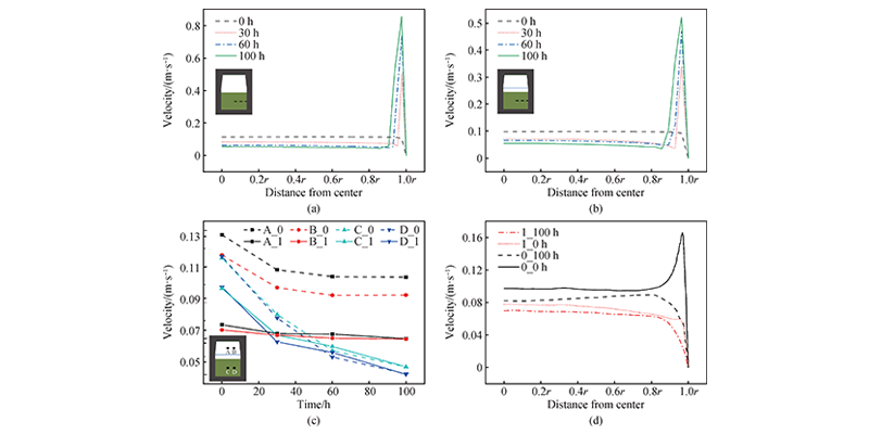
Figure 4 Changes in material flow rate. (a) Changes in the material flow rate distribution in the middle of the raw material of structure 0 at 0, 30, 60, and 100 h, r is the radius of the raw material area; (b) Changes in the material flow rate distribution in the middle of the raw material of structure 1 at 0, 30, 60, and 100 h, r is the radius of the raw material area; (c) Changes in the material flow rate inside the growth chamber (A, B) and inside the raw material (C, D) of structures 0 and 1 over time; (d) Material flow rate distribution near the seed crystal surface of structures 0 and 1 at 0 and 100 h, r is the radius of the seed crystal
C/Si affects the crystalline stability and defect density of SiC crystal growth. Figure 5(a) compares the C/Si ratio distribution of the two structures at the initial moment. The C/Si ratio gradually decreases from the bottom to the top of the crucible, and the C/Si ratio of structure 1 is always higher than that of structure 0 at different positions. Figures 5(b) and 5(c) show that the C/Si ratio gradually increases with growth, which is related to the increase in internal temperature in the later stage of growth, the enhancement of raw material graphitization, and the reaction of Si components in the gas phase with the graphite crucible. In Figure 5(d), the C/Si ratios of structure 0 and structure 1 are quite different below PG (0, 25 mm), but slightly different above PG (50 mm), and the difference gradually increases as it approaches the crystal. In general, the C/Si ratio of structure 1 is higher, which helps stabilize the crystal form and reduce the probability of phase transition.
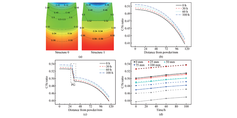
Figure 5 Distribution and changes of C/Si ratio. (a) C/Si ratio distribution in crucibles of structure 0 (left) and structure 1 (right) at 0 h; (b) C/Si ratio at different distances from the center line of crucible of structure 0 at different times (0, 30, 60, 100 h); (c) C/Si ratio at different distances from the center line of crucible of structure 1 at different times (0, 30, 60, 100 h); (d) Comparison of C/Si ratio at different distances (0, 25, 50, 75, 100 mm) from the center line of crucible of structure 0 (solid line) and structure 1 (dashed line) at different times (0, 30, 60, 100 h).
Figure 6 shows the changes in particle diameter and porosity of raw material regions of the two structures. The figure shows that the raw material diameter decreases and the porosity increases near the crucible wall, and the edge porosity continues to increase and the particle diameter continues to decrease as the growth progresses. The maximum edge porosity is about 0.99 at 100 h, and the minimum particle diameter is about 300 μm. The particle diameter increases and the porosity decreases on the upper surface of the raw material, corresponding to recrystallization. The thickness of the recrystallization area increases as the growth progresses, and the particle size and porosity continue to change. The maximum particle diameter reaches more than 1500 μm, and the minimum porosity is 0.13. In addition, since PG increases the temperature of the raw material area and the gas supersaturation is small, the recrystallization thickness of the upper part of the raw material of structure 1 is small, which improves the raw material utilization rate.
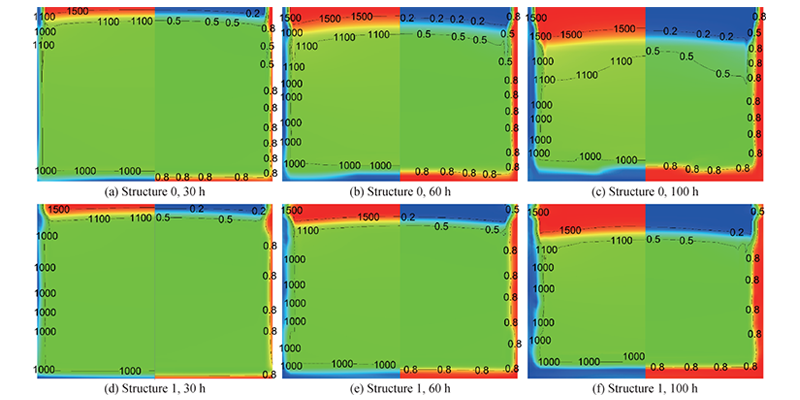 Figure 6 Changes in particle diameter (left) and porosity (right) of the raw material area of structure 0 and structure 1 at different times, particle diameter unit: μm
Figure 7 shows that structure 0 warps at the beginning of growth, which may be related to the excessive material flow rate caused by the graphitization of the raw material edge. The degree of warping is weakened during the subsequent growth process, which corresponds to the change in material flow rate at the front of the crystal growth of structure 0 in Figure 4 (d). In structure 1, due to the effect of PG, the crystal interface does not show warping. In addition, PG also makes the growth rate of structure 1 significantly lower than that of structure 0. The center thickness of the crystal of structure 1 after 100 h is only 68% of that of structure 0.
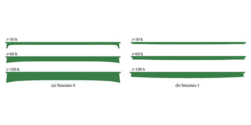
Figure 7 Interface changes of structure 0 and structure 1 crystals at 30, 60, and 100 h
Crystal growth was carried out under the process conditions of numerical simulation. The crystals grown by structure 0 and structure 1 are shown in Figure 8(a) and Figure 8(b), respectively. The crystal of structure 0 shows a concave interface, with undulations in the central area and a phase transition at the edge. The surface convexity represents a certain degree of inhomogeneity in the transport of gas-phase materials, and the occurrence of phase transition corresponds to the low C/Si ratio. The interface of the crystal grown by structure 1 is slightly convex, no phase transition is found, and the thickness is 65% of the crystal without PG. In general, the crystal growth results correspond to the simulation results, with a larger radial temperature difference at the crystal interface of structure 1, the rapid growth at the edge is suppressed, and the overall material flow rate is slower. The overall trend is consistent with the numerical simulation results.
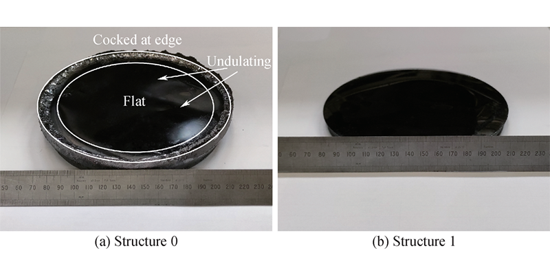
Figure 8 SiC crystals grown under structure 0 and structure 1
Conclusion
PG is conducive to the improvement of the overall temperature of the raw material area and the improvement of axial and radial temperature uniformity, promoting the full sublimation and utilization of the raw material; the top and bottom temperature difference increases, and the radial gradient of the seed crystal surface increases, which helps to maintain the convex interface growth. In terms of mass transfer, the introduction of PG reduces the overall mass transfer rate, the material flow rate in the growth chamber containing PG changes less with time, and the entire growth process is more stable. At the same time, PG also effectively inhibits the occurrence of excessive edge mass transfer. In addition, PG also increases the C/Si ratio of the growth environment, especially at the front edge of the seed crystal interface, which helps to reduce the occurrence of phase change during the growth process. At the same time, the thermal insulation effect of PG reduces the occurrence of recrystallization in the upper part of the raw material to a certain extent. For crystal growth, PG slows down the crystal growth rate, but the growth interface is more convex. Therefore, PG is an effective means to improve the growth environment of SiC crystals and optimize crystal quality.
Post time: Jun-18-2024
